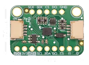
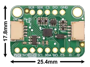
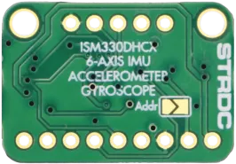
ISM330DHCX 6 Axis IMU Breakout Board
Product Description
- 6-axis motion tracking (accel + gyro)
- Accelerometer: ±2/±4/±8/±16 g, up to 6.7 kHz
- Gyroscope: ±125 to ±4000 dps, up to 6.7 kHz
- Wide temp range: -40 to +105 °C
- I²C & SPI interfaces, 3.3V or 5V logic compatible
- Two 4-pin I²C connectors compatible with Qwiic/STEMMA QT boards.
- Onboard level shifting for flexible power input
- 2 configurable interrupt pins
- Built-in state machine and machine learning for event detection, gesture recognition, and activity classification
- Sensor hub capability for interfacing additional sensors
- Backed by helpful tutorials, libraries, and examples
- Lead-Free
This ISM330DHCX breakout board delivers 6 degrees of freedom with high-precision accelerometer, gyroscope, and temperature data for accurate motion sensing and temperature compensation. It supports selectable accelerometer ranges (±2/±4/±8/±16 g) and gyroscope ranges (±125 to ±4000 dps), with update rates from 1.6 Hz to 6.7 kHz and an operating temperature range of -40 to +105 °C, making it suitable for a wide range of applications.
Advanced features include freefall, tap, and motion detection interrupts, along with integrated state machine and machine learning cores for gesture recognition and activity classification.
The board supports both I²C and SPI communication, includes two configurable interrupt pins, and can act as a sensor hub via its secondary I²C/SPI interfaces. This board includes two 4-pin JST connectors compatible with Qwiic/STEMMA QT. Onboard power regulator and level-shifting ensure compatibility with both 3.3 V and 5 V systems.
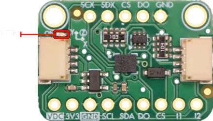
Includes an onboard LED that lights up when power is connected.

Pinout
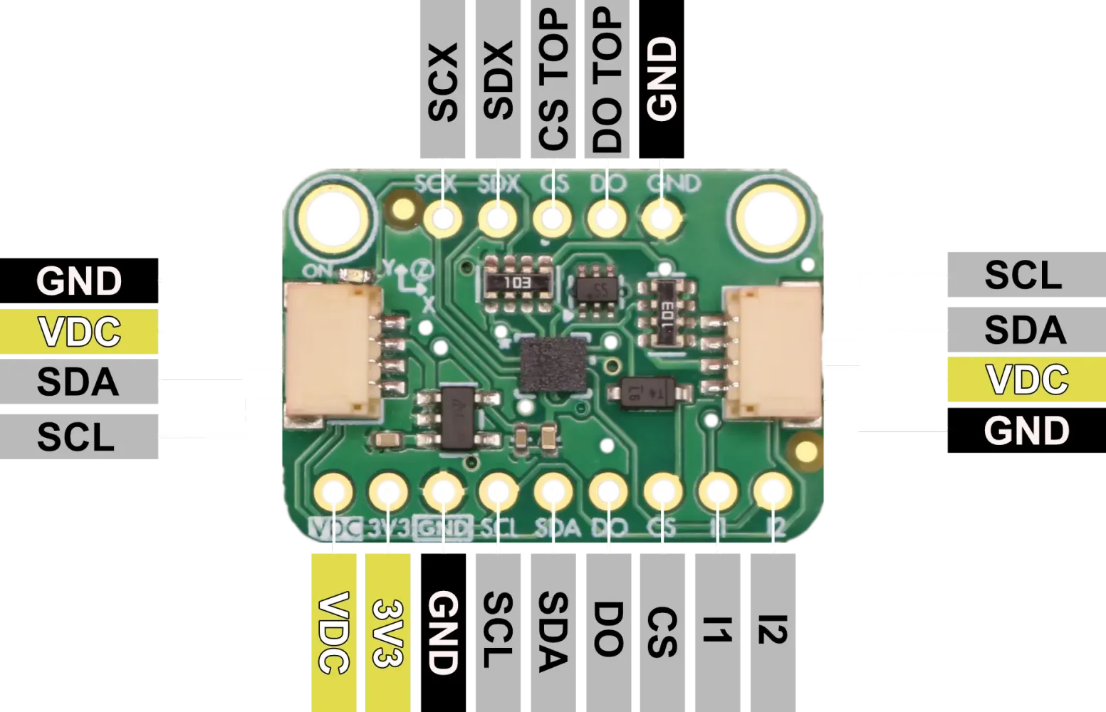
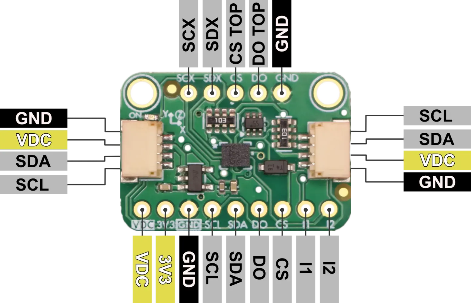
| Pin | I/O | Description |
|---|---|---|
| VDC | I | 3.3V or 5V Supply Voltage. Be sure to use the same voltage as your logic level voltage |
| 3V3 | O | 3.3V power output from voltage regulator |
| GND | - | Common GND for power and logic |
| SCL | I | I²C Serial Clock(SCL), SPI serial port clock (SPC) |
| SDA | I/O | I²C serial data (SDA),SPI serial data input (SDI), 3-wire interface serial data output (SDO) |
| DO | O | SPI 4-wire interface serial data output (SDO), I²C least significant bit of the device address (SA0) |
| CS | I | Chip Select: I²C/SPI mode selection (HIGH: SPI idle mode / I²C communication enabled; LOW: SPI communication mode / I²C disabled) |
| I1 | O | Programmable interrupt in I²C and SPI |
| I2 | O | Programmable interrupt 2 (INT2) /Data enabled (DEN) / I²C master external synchronization signal (MDRDY) |
| SCX | I | I²C serial clock master (MSCL), Auxiliary SPI 3/4-wire interface serial port clock (SPC_Aux) |
| SDX | I/O | I²C serial data master (MSDA), Auxiliary SPI 3/4-wire interface serial data input (SDI) and SPI 3-wire serial data output (SDO) |
| CS (Top) | I | Auxiliary SPI 3/4-wire chip select (CS) |
| DO (Top) | O | Auxiliary SPI 4-wire interface: serial data output (SDO) |
Voltage Compatability
The ISM330DHCX Breakout Board can operate with both a 3.3V or a 5V supply on pin VDC. Logic levels should match supply voltage for proper operation.
Communication Interfaces
I²C Communication
The ISM330DHCX supports I²C communication with two possible addresses, which can be selected using the SDO/SA0 pin or by soldering the address jumper:
- 0x6B (default when Addr jumper is open, DO high)
- 0x6A (when Addr jumper is closed, DO low)
The I²C interface supports standard (100 kHz), fast (400 kHz), and fast-plus (1 MHz) mode clock speeds. Onboard pull-up resistors are included on both SCL and SDA lines.
SPI Communication
For SPI communication, the ISM330DHCX supports both 3-wire and 4-wire SPI modes:
- SCL/SPC: Serial Clock
- SDA/SDI: Serial Data Input (MOSI)
- SDO: Serial Data Output (MISO)
- CS: Chip Select (active low)
SPI clock frequencies up to 10 MHz are supported.
Operation Modes
The ISM330DHCX offers 4 distint functional operation modes:
- Mode 1 provides either I²C or SPI (3-/4-wire) serial interface for basic communication.
- Mode 2 adds the capability for the ISM330DHCX to act as an I²C master, enabling connection to external sensors while still supporting I²C or SPI for the host interface.
- Mode 3 maintains I²C or SPI communication with the host but adds an auxiliary SPI interface specifically for the gyroscope, useful in optical image stabilization (OIS) applications.
- Mode 4 extends Mode 3 by enabling auxiliary SPI output for both accelerometer and gyroscope data, offering full external sensor interfacing through SPI. These flexible operation modes allow the device to support a wide range of use cases, from simple sensor integration to complex, real-time stabilization systems.
Mode 1: Basic Operation
I2C operation
The ISM330DHCX supports I²C communication as a target device, requiring two lines: SCL (clock) and SDA (data), both pulled up with onboard 10 kΩ resistors. The I²C device address is configurable using the SDO/SA0 pin, which sets the least significant bit of the address using the jumper on the backside of the board. By default, when SDO/SA0 is connected to GND, the 7-bit I²C address is 0x6A (8-bit write: 0xD4, read: 0xD5). When jumpered to Vdd_IO, the address changes to 0x6B (8-bit write: 0xD6, read: 0xD7). This allows two ISM330DHCX devices to coexist on the same I²C bus.
SPI operation
The ISM330DHCX supports SPI communication in both 3-wire and 4-wire modes.To enable SPI mode, the CS (Chip Select) pin must be held low. In 4-wire mode, the required pins are CS, SCL (clock), SDA (data input), and SDO (data output). In 3-wire mode, SDI and SDO are combined into a single bidirectional data line. The mode is selected by setting the SIM bit (bit 0) in the CTRL3_C register at address 0x12—SIM = 0 selects 4-wire SPI (default), and SIM = 1 enables 3-wire SPI. This bit can be set using either I²C or 4-wire SPI.
Mode 2: Sensor Hub
Mode 2 of the ISM330DHCX is the Sensor Hub, allowing the device to act as an I²C master to communicate with up to four external sensors in addition to its built-in accelerometer and gyroscope. In this configuration, the ISM330DHCX uses its dedicated MSCL (master clock, SCX) and MSDA (master data, SDX) lines to interface with external I²C devices, enabling synchronized data collection. The sensor hub can autonomously collect, batch, and forward data from external sensors to the host via the primary I²C or SPI interface, reducing host processor load and improving efficiency. Mode 2 is ideal for applications requiring fusion of data from multiple sensor types, such as magnetometers or environmental sensors.
Connect External Sensors
- Wire the external I²C sensors to the ISM330DHCX’s MSCL (SCX) and MSDA (SDX) pins.
- Ensure all devices share a common ground and appropriate pull-up resistors are present on the I²C lines.
Configure Sensor Hub Registers
- Use your microcontroller (host) to communicate with the ISM330DHCX via its primary I²C or SPI interface.
- Set up the following registers:
- SLV0_ADD, SLV0_SUBADD, SLV0_CONFIG: Configure the address, sub-address (register), and number of bytes to read from the first external sensor.
- Repeat for SLV1, SLV2, SLV3 if using more sensors.
- SENSOR_HUBx_REG: These registers will hold the data read from external sensors.
Enable Sensor Hub
- Set the FUNC_CFG_ACCESS register to enable access to embedded functions.
- Set the MASTER_ON register to 1 to enable the sensor hub master.
- Optionally, configure the ODR (output data rate) for the sensor hub.
Trigger Data Acquisistion
- The ISM330DHCX will automatically read from the external sensors at the configured ODR.
- Data from external sensors is stored in the SENSORHUB[x]_REG registers.
- Optionally, use the MDRDY/INT2 pin or poll the status register to know when new data is available.
See ISM330DHCX data sheet for more infomation about setting up Sensor Hub.
Alternate Master Modes 3 & 4: Auxiliary SPI Output
The ISM330DHCX supports advanced operation modes that enable an auxiliary SPI interface for direct, high-speed access to sensor data. In these modes, the device maintains standard I²C or SPI communication with the host microcontroller, while simultaneously streaming motion data over the auxiliary SPI interface to an external processor or controller.
Auxiliary SPI Modes:
- Gyroscope Only: The auxiliary SPI interface outputs only gyroscope data. This is ideal for applications such as optical image stabilization (OIS), where low-latency gyroscope data is required.
- Gyroscope and Accelerometer: Both gyroscope and accelerometer data are streamed over the auxiliary SPI interface, providing comprehensive motion data for real-time processing.
How to Use Auxiliary SPI Modes:
- Hardware Connection: Connect the auxiliary SPI pins (SCX, SDX, CS, and DO) of the ISM330DHCX to your external controller or processor.
- Configuration:
- Use your host microcontroller to configure the ISM330DHCX via the main I²C or SPI interface.
- Select whether to output only gyroscope data or both gyroscope and accelerometer data over the auxiliary SPI.
- Operation:
- The main I²C or SPI interface remains available for standard communication with the host.
- The auxiliary SPI interface provides a continuous, low-latency data stream for real-time applications.
Refer to the ISM330DHCX datasheet for detailed register settings, timing diagrams, and further configuration details for auxiliary SPI operation.
Interrupt pins
The ISM330DHCX features two configurable interrupt pins, INT1 and INT2, which provide flexible signaling options for a wide range of applications. These pins can be programmed to output various interrupt signals generated by the device’s internal logic, allowing the host microcontroller to respond promptly to specific sensor events without constant polling.
Common uses for the interrupt pins include:
-
Freefall Detection: The device can generate an interrupt when it detects a freefall event, which is useful for drop detection in portable electronics or safety systems. When enabled, the ISM330DHCX monitors acceleration levels and triggers an interrupt if the measured acceleration falls below a programmable threshold for a specified duration.
-
Tap Detection: The ISM330DHCX can recognize single and double tap events on any axis. When a tap is detected, an interrupt is generated, enabling gesture-based user interfaces or wake-on-tap functionality in low-power applications.
-
Motion Detection: The sensor can be configured to detect motion or inactivity. For example, it can trigger an interrupt when movement is detected after a period of stillness, or when the device becomes stationary. This is useful for power management, activity monitoring, or event logging.
-
Orientation and Activity Recognition: The ISM330DHCX’s state machine and machine learning core can classify activities (such as walking, running, or cycling) and detect orientation changes, generating interrupts for these events as well.
-
FIFO Thresholds and Data Ready: Interrupts can also be configured to signal when new data is available, when the FIFO buffer reaches a certain level, or when specific sensor data is ready to be read.
Both INT1 and INT2 pins can be independently mapped to different interrupt sources using the device’s control registers, allowing for highly customizable event signaling. The polarity, output type (push-pull or open-drain), and latching behavior of the interrupt pins are also configurable to match system requirements. For detailed configuration steps and register settings, refer to the ISM330DHCX datasheet and application notes. See examples to get started with interrupts.
How to Implement Interrupt Examples
To use these interrupt features, you typically need to:
- Configure the relevant interrupt source in the ISM330DHCX registers (for example, enabling freefall detection and setting thresholds).
- Map the interrupt source to INT1 or INT2 using the appropriate control registers (such as
MD1_CFGorMD2_CFG). - Set the pin behavior (polarity, push-pull/open-drain, latching) in the
CTRL3_Cand related registers. - Monitor the INT1/INT2 pin on your microcontroller and handle the event in your firmware.
ST provides example code and application notes to help you get started:
For more details on register settings and advanced configuration, refer to the ISM330DHCX datasheet and application notes.
State Machine and Machine Learning
The ISM330DHCX features both a programmable Finite State Machine (FSM) and a Machine Learning Core (MLC) for advanced, low-power event detection and activity classification directly on the sensor. These embedded engines allow you to offload complex motion processing from your host microcontroller, enabling always-on gesture, activity, or context recognition with minimal power consumption.
Finite State Machine (FSM)
The FSM is a flexible logic engine that can monitor accelerometer and gyroscope data to detect user-defined motion patterns or sequences. Up to 16 independent state machines can be configured, each capable of recognizing specific events such as wrist tilt, step counting, or custom gestures. The FSM is programmed by uploading a sequence of instructions (FSM programs) to the device using dedicated registers.
How to implement FSM use cases:
- Design your event logic using ST’s Unico-GUI or FSM programming tools, which allow you to visually create and simulate state machines.
- Export the FSM program and load it into the ISM330DHCX using your microcontroller or ST’s tools.
- Enable the FSM by setting the appropriate control registers (such as
FSM_ENABLE_A/B). - Map FSM output interrupts to INT1 or INT2 pins using the
MD1_CFGorMD2_CFGregisters. - Monitor the interrupt pin or read the FSM status registers to detect when your event is recognized.
Machine Learning Core (MLC)
The MLC enables real-time activity recognition using decision tree models trained on sensor data. You can use ST’s NanoEdge AI Studio or Unico-GUI to collect data, train a model (for example, to distinguish between walking, running, cycling, or stationary), and export the configuration for the ISM330DHCX.
How to implement MLC use cases:
- Collect labeled sensor data for your activities using Unico-GUI or NanoEdge AI Studio.
- Train a decision tree model using the collected data in the software tool.
- Export the MLC configuration (a set of register values) and load it into the ISM330DHCX via your microcontroller.
- Enable the MLC by setting the appropriate control registers.
- Map MLC output interrupts to INT1 or INT2, or read the MLC status registers to determine the recognized activity.
Typical Use Cases
- Gesture recognition (e.g., wrist tilt, double tap, shake)
- Activity classification (e.g., walking, running, cycling, stationary)
- Custom event detection (e.g., posture changes, specific movement patterns)
- Power-efficient wake-up and context-aware applications
For more details, see the ISM330DHCX application note and the ST example code repository.
Software Libraries and Examples
We at Stardust have created an arduino library and examples to get you started with the ISM330DHCX breakout board. Please follow the links these files.
- Stardust Arduino library and examples coming soon!
- ST ISM330DHCX Examples (GitHub)
Datasheets, Schematics, and More
Schematic:
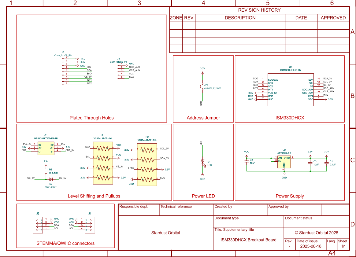
Chip Info and Product Datasheets:
- STMicroelectronics ISM330DHCX Datasheet
- STMicroelectronics ISM330DHCX Application Notes
- STMicroelectronics ISM330DHCX Product Page
Store Page: