BNO085 9 Axis IMU Breakout Board
Product Description
Experiment with sensor fusion IMUs with the BNO085 Breakout Board.
- Sensor-Enabled: 9-axis accelerometer, gyro, and magnetometer provides precise motion tracking.
- Ready for Prototype: Common reports (e.g. Rotation Vectors) native to the BNO085 firmware coupled with STRDC’s library makes startup easy.
- Reliable: Dynamic calibration adjusts for changes over time and temperature.
- Application Ready: The BNO085 generates activity tracking reports for quick bring-up of step-counting and heart-rate monitoring.
- Power Conscious: Power management features like sleep and wake-on-motion maximize application requirements.
- Universal: Interface with I²C (QWIIC/Stemma Compatible), SPI, or UART. Includes a 5V to 3.3V level shifter and 5V to 3.3V power regulator.
- Lead-free
Features
- BNO085 9-Axis IMU (Accelerometer, Gyroscope, Magnetometer), separate I²C bus for environmental sensors
- Pre-installed sensor-fusion applications for Rotation Vectors, AR/VR Stabilization, Step-Counting, etc…
- Communicate over I²C, SPI, UART, or UART-RVC
- STRDC library for quick setup
- Compatible with 5V and 3.3V
- 3.3V power regulator
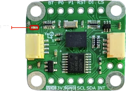
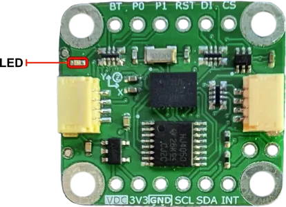
- Onboard LED to indicates power is applied
- Lead-Free
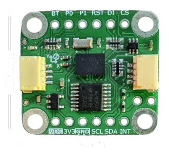
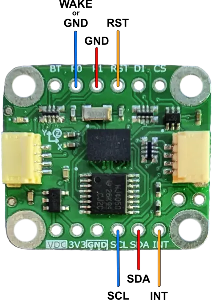
Pinout
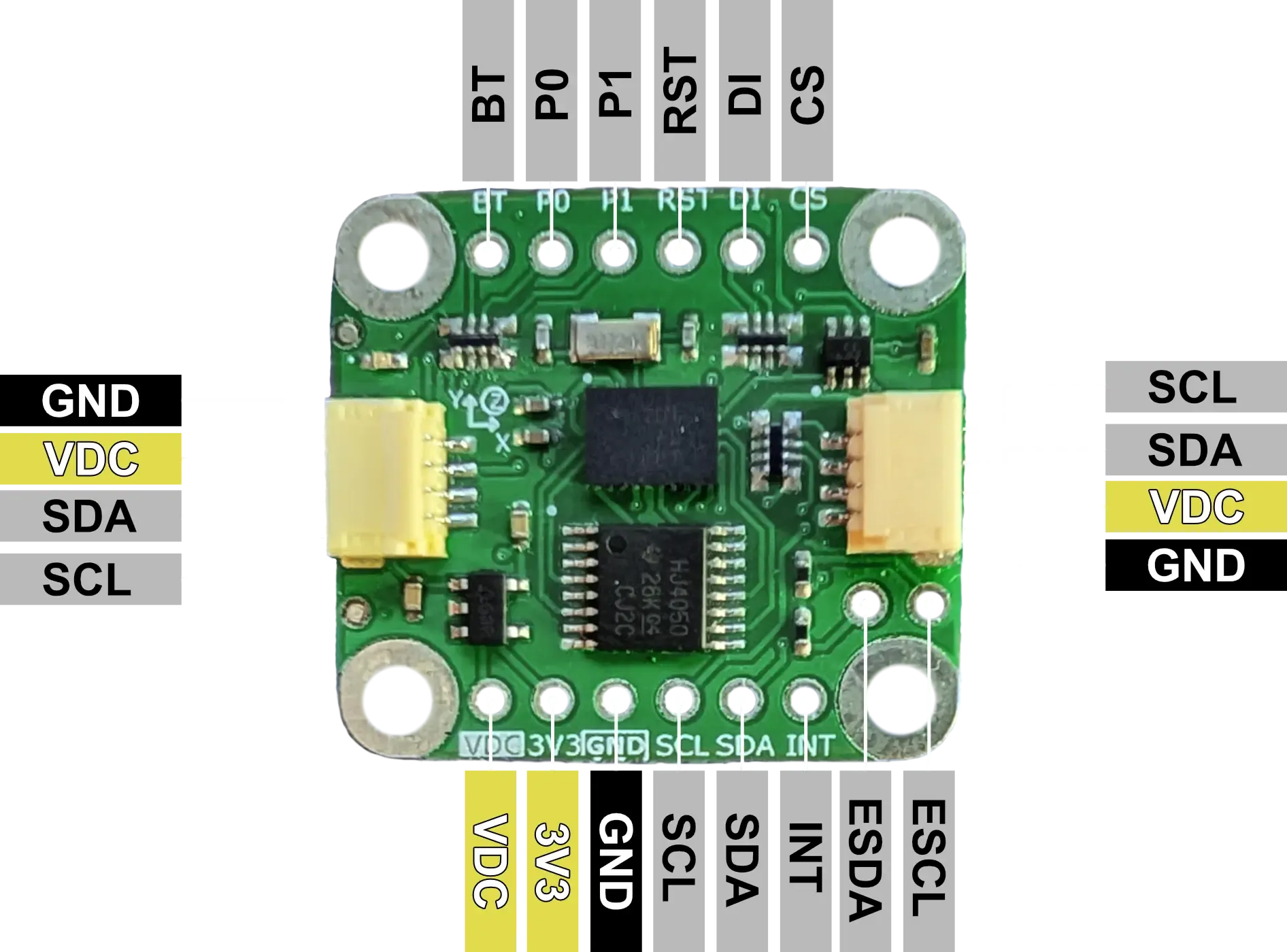
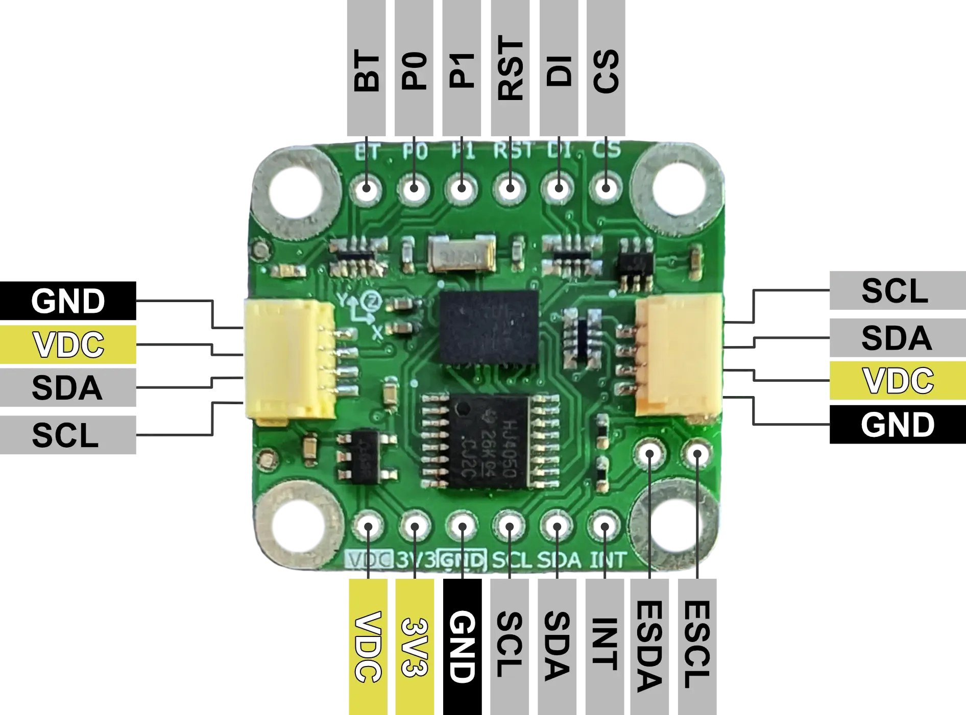
| Pin | I/O | Description |
|---|---|---|
| VDC | I | 5V or 3.3V supply voltage matching communication logic level. |
| 3V3 | O | 3.3V output from 5V to 3.3V power regulator (100mA max). |
| GND | - | Ground |
| SCL | I/O | I²C: SCL. SPI: SCK. UART: BNO085 TX. UART-RVC: NC. |
| SDA | I/O | I²C: SDA. SPI: MISO. UART: BNO085 RX. UART-RVC: BNO085 RX. |
| INT | I | Interrupt from BNO085 (active low). |
| CS | I | SPI: Chip Select. |
| DI | I/O | I²C: Lower bit of address. SPI: MOSI. |
| RST | I | BNO085 Reset (active low), connected to VDC with 10kΩ pullup. |
| P1 | I | BNO085 PS1 pin for communication configuration. I²C: LOW. SPI: HIGH. UART: HIGH. UART-RVC: LOW. |
| P0 | I | BNO085 PS0/Wake pin for communication configuration. I²C: LOW. SPI: HIGH. UART: LOW. UART-RVC: HIGH. |
| BT | I | BNO085 Bootloader Mode Select at power-up. Normal: HIGH. Bootloader: LOW. |
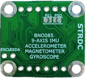
| ESCL | - | Environmental Sensor I²C SCL. |
| ESDA | - | Environmental Sensor I²C SDA. |
Voltage Compatibility
The BNO085 Breakout Board can operate with both a 3.3V or a 5V supply on pin VDC. Logic levels should match supply voltage for proper operation.
Communication Interfaces
I²C
- I²C Address: The LSb of the address can be selected using the DI pin (LOW: 0x4A, HIGH: 0x4B), implement the intended configuration before power-on.
- Clock Speed: Up to 400 kHz
- Pull-up Resistors: Onboard 10kΩ pull-ups included
- Connector: 4-pin 1mm pitch JST QWIIC/Stemma Compatible connector
SPI
- Clock Speed: Up to 3 MHz
- SPI Mode: SPI Mode 3 (CPOL = 1, CPHA = 1)
UART
- Operating Baud Rate: 3Mbaud
- Data Format: 8 data bits, no parity, 1 stop bit
- Protocol: CEVA SHTP
UART-RVC
- Operating Frequency: 100 Hz
Interrupt Functionality
The BNO085 asserts the INT pin when it needs attention from the host (has data to send, needs to report an error, etc…). The pin will be asserted until the I²C address has been received on the bus or the SPI CS pin is asserted.
Environmental Sensors
The BNO085 can communicate with external sensors on a separate I²C bus (broken out by ESCL and ESDA) and report them similar to its internal sensors. Review the BNO08x datasheet for more details and a complete list:
- Bosch Sensortec BME280 pressure/humidity/temperature sensor
- Bosch Sensortec BMP280 pressure/humidity/temperature sensor
- Capella Microsystems CM36686 proximity and ambient light sensor
Software Library and Examples
To expedite prototyping, STRDC has created a BNO08x library included in our STRDC SDK. The library includes many examples that may be used to start prototyping or explore the full functionality of the BNO085. In addition to the library, the SDK also includes a HAL for the Teensy4.1 (Teensyduino) and common drivers for everything needed to communicate with the BNO085.
Examples on ArduinoIDE
To get started with the ArduinoIDE examples, ensure that the HAL, Drivers, and BNO08x Module are in the local Arduino libraries location. From there, compile and upload the example sketch.
Examples on PlatformIO
To get started with PlatformIO examples,
-
Create a new PlatformIO project selecting the target device and framework (Teensy4.1 and Arduino if using the HAL included in the SDK).
-
Update the platformio.ini file to include necessary dependencies (
lib_deps) -
Add additional necessary dependencies to the
libdirectory of the project (the HAL (if using Teensyduino) and Drivers in the SDK). -
Add the desired example program
main.cppto thesrcdirectory of the project. -
Compile and upload.
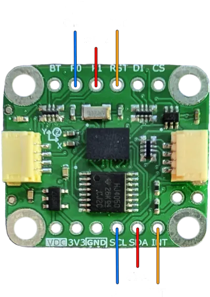
Connections
The device used to communicate with the breakout board will be referred to as “host”.
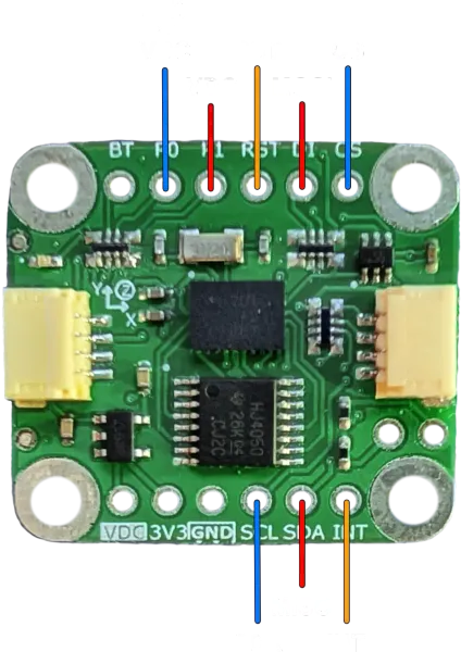
I²C
Connect the host to the breakout board as shown (VDC and GND connection are omitted).
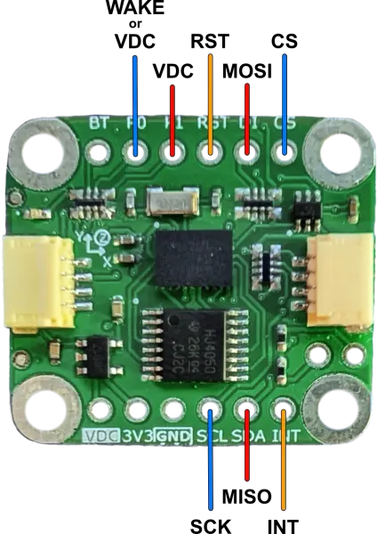
SPI
Connect the host to the breakout board as shown (VDC and GND connection are omitted).
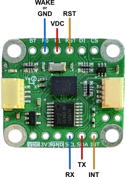
UART
Connect the host to the breakout board as shown (VDC and GND connection are omitted). RX and TX are the Host RX and TX.
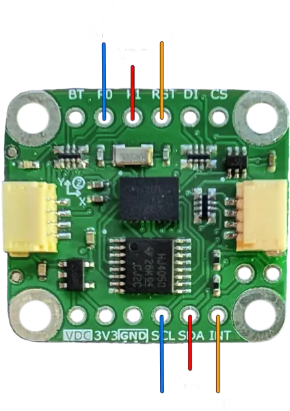
UART-RVC
Connect the host to the breakout board as shown (VDC and GND connection are omitted). RX and TX are the Host RX and TX.
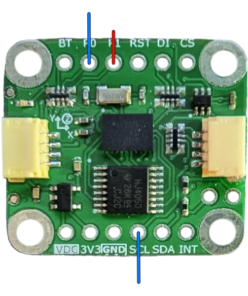

Use the specific UART_RVC example in the STRDC BNO08x library for this configuration.
Datasheets, Schematics, and More
STRDC BNO08x Library:
Schematic:
Chip Info and Product Datasheets:
- CEVA BNO085 Product Page
- CEVA BNO08X Datasheet
- CEVA SH-2 Reference Manual
- CEVA Sensor Hub Transport Protocol
Store Page:
FAQ
Q: Can I use multiple BNO085 IMUs on the same I²C bus?
A: Yes, the STRDC SDK includes an example for using multiple BNO085s (SPI and I²C). This example can be modified to be used with two BNO085s configured in I²C mode on the same bus, provided their addresses are configured differently.