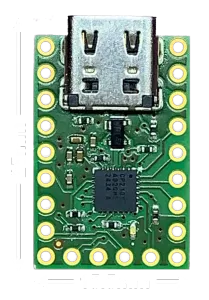
UBT-100 USB-C to UART Adapter
Product Description
- Easily establish communication with this USB-C to UART(TTL) serial adapter. Max transmission speed up to 3Mbaud
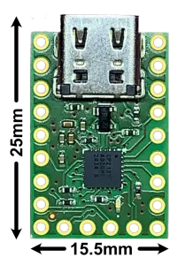
- Universal: Utilizes a USB-C receptacle for common cable connections
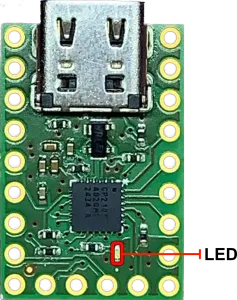
- Reliable: Uses CP2102N to avoid issues with FTDI drivers. LED indicator when port is opened
- Versatile: 5V output from USB, default 3.3V output logic (configurable to voltages lower than 3.3V), configurable GPIO, clock output, Reset, hardware flow control pins RTS, CTS, DSR, DTR, and DCD
- Supported: All pinouts needed to support RS-232, RS-422, and RS-485
Easy to use for engineers and hobbyists alike. Communicates with USB 2.0 but is compatible with USB 3.0. Onboard LED lights up after a serial port connection is made.
Features
- CP2102N USB-C to UART (TTL) Serial Adapter
- Max transmission speed up to 3Mbaud
- Compatible with RS-232, RS-422, RS-485
- Configurable GPIO, RS-485 Enable/Disable, Clock Output
- 5V and 3.3V outputs
- Configurable logic level from 3.3V down to 1.8V, compatible with some 5V logic devices
- Onboard LED to indicate serial port connection
- Lead-Free
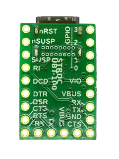
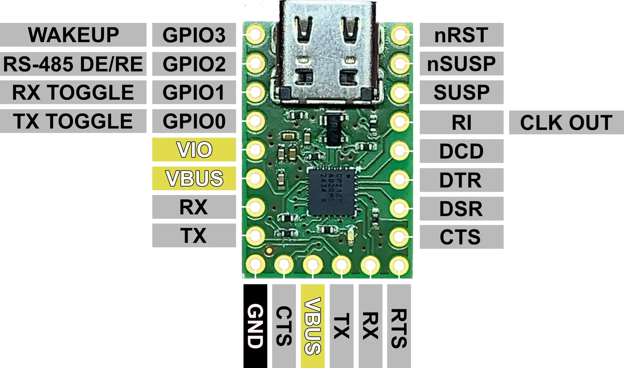
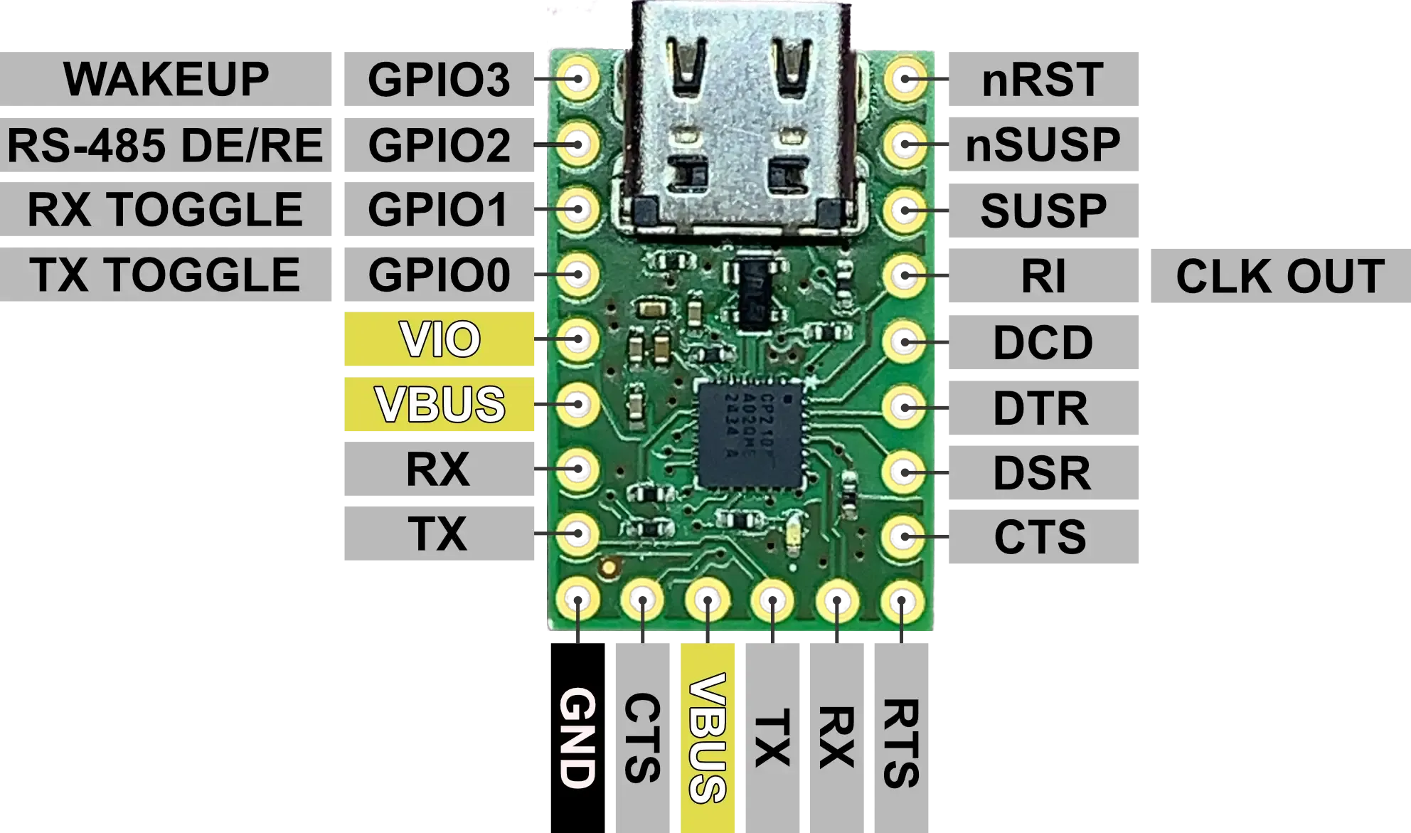
Pinout
| Pin | I/O | Description |
|---|---|---|
| GPIO3/WAKEUP | I/O | GPIO3: General Purpose I/O. WAKEUP: Remote USB Wakeup Interrupt Input (active low). |
| GPIO2/RS-485 DE/RE | I/O | GPIO2: General Purpose I/O. RS-485 DE/RE: RS485 Control Signal. |
| GPIO1/RX TOGGLE | I/O | GPIO1: General Purpose I/O. RX TOGGLE: Receive LED Driver. |
| GPIO0/TX TOGGLE | I/O | GPIO0: General Purpose I/O. TX TOGGLE: Transmit LED Driver. |
| VIO | I/O | Output from 3.3V Output and I/O Supply Power Input - See Output Voltage Select and Compatability |
| VBUS | O | 5V Output from USB |
| RX | I | UART Receive Digital Input |
| TX | O | UART Transmit Digital Output |
| GND | - | Ground |
| CTS | I | Clear to Send Control Input (active low) |
| RTS | O | Ready to Send Control Output (active low) |
| DSR | I | Data Set Ready Control Input (active low) |
| DTR | O | Data Terminal Ready Control Output (active low) |
| DCD | I | Data Carrier Detect Control Input (active low) |
| RI/CLK OUT | I/O | RI: Ring Indicator digital input (active low). CLK OUT: Digital Clock Output. |
| SUSP | O | Driven High When Entering USB Suspend State |
| nSUSP | O | Driven Low When Entering USB Suspend State (This pin is connected to the LED) |
| nRST | I | Reset (active low), connected to VIO with 1kΩ pullup |
Output Supply Voltages
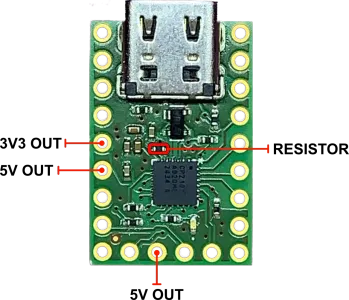
In the pre-assembled configuration, UBT-100 outputs 3.3V on the VIO pin and 5V on the VBUS pin.
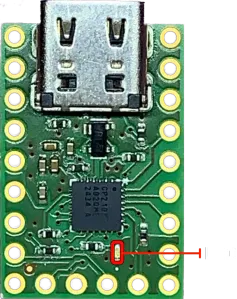
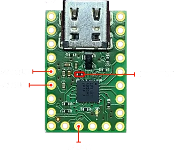
Output Voltage Select and Compatability
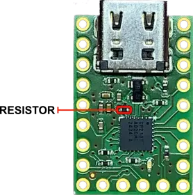
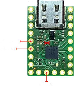
As assembled, UBT-100 connects the CP2102N VIO pin with the 3.3V regulator output via a 0-ohm resistor. This puts the IC in a 3.3V logic configuration for the non-power and non-USB pins. In this configuration, the IC can tolerate 5V signals on these pins, allowing compatibility with 5V logic devices (assuming their HI output threshold is lower than 3.3V).
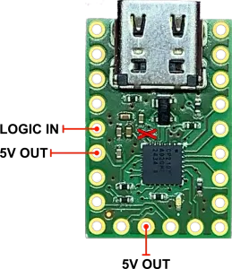
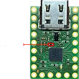
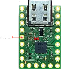
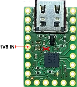
The logic level of UBT-100 can be made configurable by removing the indicated 0-ohm resistor, and supplying the VIO pin with the desired logic voltage (min. 1.8V, max 3.3V). In the 1.8V logic configuration, the non-power and non-USB pins can tolerate 3.3V, but will be unable to output voltages sufficient for 3.3V logic. Note: In the 1.8V logic configuration, the CP2102N cannot tolerate 5V signals on the non-power and non-USB pins.
UART Connections
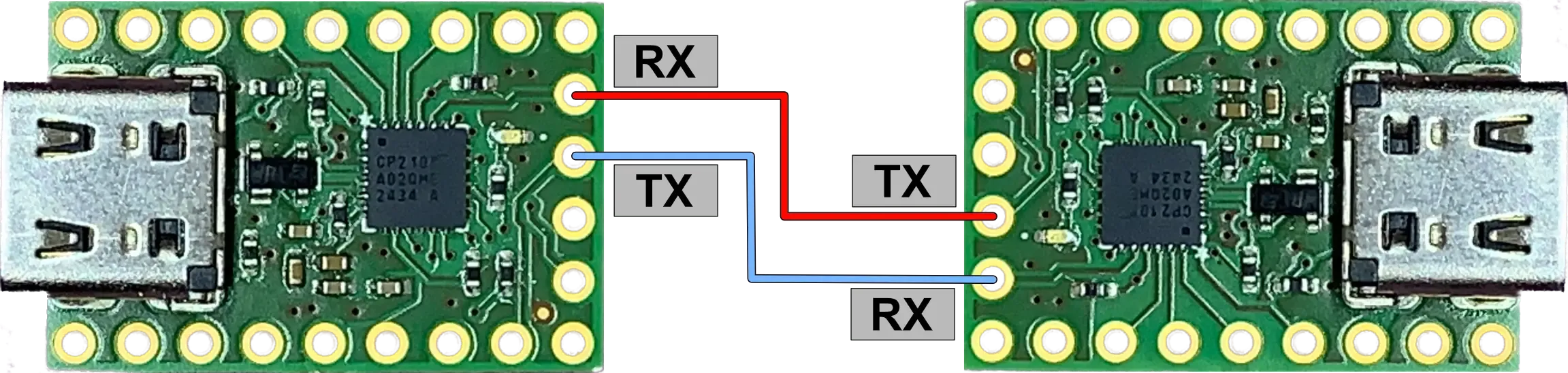
For new users of UART, see the example connection diagram - in this case, two UBT-100s. The RX pin for each device should be connected to the opposing device’s TX pin. Now each device will transmit to the opposing device’s receiving pin.
Driver Installation
Install CP210x Driver on Silicon Labs website (e.g. Universal Windows Driver). After installation, the device will appear as a serial port (COMx in Windows, /dev/tty in Linux) and the basic serial parameters (e.g. Baudrate) can be modified (e.g. through Windows Device Manager).
Additional Features and Alternate Pin Functions
To gain full access to the configuration, install Simplicity Studio as provided by Silicon Labs.
-
After downloading, open the .iso file and run setup.exe. Complete the installation via the installer.
-
After installation, open Simplicity Studio. Download the recommended updates, this may require multiple restarts of the program. Upon reaching the Welcome/Launcher page, if UBT-100 is already connected to the computer, the CP2102N IC will show up in the Connected Devices section. With the device selected, click “Start” to show an overview of the IC, then click “Create New Project”.
-
Ensure the Project Wizard has “Custom Board” selected for Target Boards and that “CP2102N-A02-GQFN24” is selected as the Target Device.
-
Click through the wizard, selecting the empty project option and location to save the project, then hit “Finish”. This should bring up a new page for the CP2102N. Here, the full feature set of the CP2102N may be configured.
-
After selecting the desired configuration, with the device plugged in and any other serial connections terminated (e.g. Realterm, Putty, etc…), click the “Program To Device” button to upload the configuration to the CP2102N EEPROM. After a few seconds, the device may now be used with the new configuration.
Silicon Labs provides an API for controlling GPIOs, but this is beyond the scope of this document.
Datasheets, Schematics, and More
Schematic:
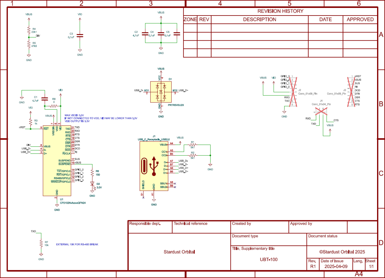
Chip Info and Product Datasheets:
- Silicon Labs CP2102N Datasheet
- Silicon Labs CP210x Driver
- Silicon Labs Simplicity Studio
- Silicon Labs CP2102N Product Page
Store Page: